You may be wondering, how does radon mitigation work in a home without drain tile? Homes with drain tile are typically easier to mitigate than homes without drain tile. If your home does not have drain tile you will likely need a mitigation system that falls into the sub-slab depressurization category of radon systems.
This blog post will discuss the process to mitigate a house in Stillwater, MN. At over 6,200 square feet and without drain tile, this project was a bit of a challenge. Read on to see how we took their levels from over 5 pCi/L to less than 1 pCi/L.

THE GOAL
For anyone unfamiliar, radon is a radioactive gas released from the decay of uranium in the soil and can be naturally drawn into your home. Radon is a leading cause of lung cancer in the US, second only to smoking. You can learn about radon testing here. The EPA recommends mitigating levels at or above 4.0 pCi/L. However, there is no safe amount of radon exposure.
Our goal is to engineer and install highly effective systems that lower the radon levels in your home as much as possible to keep you and your family safe.
What is the key to engineering a highly effective system? A mitigation system works by creating suction under your home to draw the radon into the mitigation system before it has a chance to enter your home. While it’s a simple idea, in theory, there is a lot of thought and planning involved to ensure optimal performance.
SEALING GAPS AND CRACKS
We start the project by sealing gaps and cracks open to the soil. Sealing helps create better suction under your home, which in turn helps the system run more effectively. It also increases energy efficiency by reducing the amount of conditioned air leaving your home, saving you money on operating costs.
We also seal what’s known as a plumbing block-out—a one-foot by one-foot hole open to the soil under your bathtub or shower.

To seal large openings like this one, we use expanding foam. However, using too much foam could actually lift the tub. We like to use window and door foam when sealing shower pans because it doesn’t expand nearly as much as regular expanding foam.

MEASURING PRESSURE FIELD EXTENSION
Next, we move on to pressure field extension testing, which measures how far suction reaches under the house and how strong that suction is. Running these tests helps determine the best location for a suction point and the possible need for additional suction points or stitching. (More on that later.)
We start by drilling diagnostic test holes throughout the house.

We insert tubes into the holes as pictured below and plug the tubing into our micromanometers, which allow us to measure the pressure below the slab in each area of your home.

Next, we select a potential suction point to test, drill a 1.5-inch hole and apply suction to the soil using a pitot tube and shop vac.

The pitot tube allows us to measure how much air we are drawing from the soil. In this instance, we were moving 35 CFM.

Next, we check our pressure field extension in the test holes we drilled earlier. Ideally, we’d like at least -5 pascals (Pa) in each area of the house. In this case, we test two potential suction point locations to see how each one would affect our test holes, and, based on our readings, the location near the door in the storage room gives us the best overall pressure field extension.
After that, we core a five-inch hole through the floor and excavate about forty gallons of material to create our suction point. Finally, we rerun the pitot tube test to see the suction pit’s impact on our test holes.

STITCHING
We still are not getting the pressure field extension that we want everywhere in the home. We can add additional suction points to increase our pressure field extension in some homes, but this home has a finished basement, and running pipe through finished areas would be obtrusive. So instead, we decide to move forward with stitching.
Stitching refers to the process of creating a trench under the slab that allows us to reach areas of the home where it’s impractical or unsightly to run piping. To dig our trench, we drill a series of five-inch holes every two or three feet. Then we use an auger to loosen the soil and a vacuum to remove it from below the slab.

Once we finish removing the material, we plug the holes using circular pieces of foam board. Next, we use a long Tapcon screw to provide support and fill the rest of the hole with concrete. The stitching holes will be undetectable once the carpet is put back in place.

REACHING NORTH SIDE OF HOME
While the stitching helps us reach the south side of the house, we are still not getting the best pressure field extension on the north side. However, we can use the bathtub on that side of the home to our advantage.
When plumbers install sub-slab plumbing, they dig a trench to lay their pipes in. Fortunately, the soil around those pipes often settles, leaving a gap between the soil and the bottom of the concrete floor, which provides a great place to draw air from increasing the reach of our radon mitigation system.
Remember that plumbing block out from earlier?

Before sealing the block-out, we made it a suction point by filling it with rock and foamed the top to make a seal. Then, we conduct the same pitot tube test we did earlier and reach all but one of our test holes.
We found that the test hole in which we aren’t getting sufficient suction has an unsealed floor-to-wall joint behind the wall. After discussion with the homeowner, he decides to leave the floor-to-wall joint unsealed rather than pull up the carpeting in the bedroom.
Next, we stitch from the bathtub, down the hallway, and into the storage room to another suction point.

TEMPORARY RADON MITIGATION SYSTEM
For larger projects like this one, we sometimes find installing a temporary system to see how well everything functions. To do this, we connect flexible ducting to one of our suction points, run it out a window, and connect it to a radon fan.

Then, we set up radon tests to see how the radon levels are affected when the temporary mitigation system is running. For this project, we set up two tests: one on each side of the house.
Looking at the report, radon levels were around 5 pCi/L when we started the project. Levels lowered during the first day of work but rose again overnight while the house was closed up. The next day, we installed the temporary system and left it running overnight. That night, levels stayed relatively low.
At this point in the process, both radon tests are reading 0.6pCi/L, indicating that our system should be effective.

INSTALLING RADON VENT PIPE
Now that we are confident the mitigation system will reach under the entire house, it is time to install our vent pipe.
Vent piping must be secured every ten feet vertically and four feet horizontally to meet mitigation standards. We use 2-hole straps, J hooks, and pipe hangers to ensure that everything is secure and pitched properly.

Next, we install a manometer, a visual gauge that indicates whether or not the radon fan is creating suction. When the system is working, the suction from the radon fan will draw the red fluid up to be uneven. If the red fluid is level at 0, the system is not working properly, as shown in the photo below.

We also install an airflow alarm, a gauge with a flap that goes into the pipe. When there’s air moving through the system, it lifts the flap up. If there is no airflow, the flap will fall, alerting you within thirty seconds.

Lastly, we add valves to each suction point, which allow us to balance the system. For example, if we need to create more suction on the south side of the house, we could close the north side suction point valve a bit.

FIREWALL GUIDELINES
Next, we run the vent piping from the storage room to the garage through a fire-rated wall, which means we need to install a firestop collar to maintain the wall’s integrity. In the event of a fire in the garage, the radon pipe would melt away, and the intumescent material on the firestop collar would expand to close off the opening and protect the home and people inside from smoke and fire.
To install, we cut a five-inch hole for our 4-inch pipe to leave room for smoke sealant. The smoke sealant fills the 1/4-inch gap between the outside of the vent pipe and the drywall. It should be at least the depth of the drywall. Next, we slide the firestop collar onto the pipe and secure it to the rim joist using screws with one-inch fender washers. Finally, we secure a firestop collar on the ceiling, using toggle bolts with one-inch fender washers.

When running piping in the garage or attic, we wrap it in insulation. It prevents condensation from dripping on the drywall and minimizes the risk of freezing. Insulation also helps dampen noise from the system.

RADON FAN INSTALLATION
The vent piping continues up to the garage attic from the garage, where we install the radon fan.

We use an adjustable speed fan, which allows us to fine-tune the fan’s power to balance radon reduction with energy efficiency. We also add a noise suppressor in this system, which can reduce noise by up to 75 percent. Lastly, according to code, an outlet must be located within six feet of the fan along with a light. A licensed electrician will pull a permit and do this work.

From here, the vent pipe runs up through the roof of the home to exhaust outside. AARST has specific standards that dictate where the radon exhaust can be.
Finally, we paint the vent pipe to match the shingles. This way, the pipe is more aesthetically pleasing and absorbs more heat from the sun to help prevent it from freezing in the winter.

ADDITIONAL SEALING
As we mentioned at the beginning of this post, sealing is imperative for creating a radon mitigation system that’s effective and efficient. It was how we began our project, and it is our final step before wrapping up.
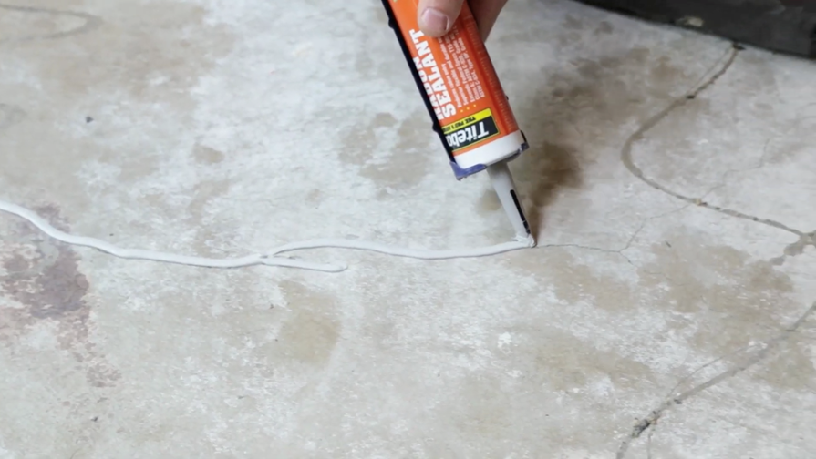
Since the homeowner is replacing some carpeting, we can seal gaps or cracks where we are losing suction. First, we used expanding foam for little areas that were hard to reach, such as under the baseboard and drywall. Then, for control joints and cracks in the floor, we used a low-VOC Radon Sealant. As an Amazon Associate, we earn from qualifying purchases.

RADON MITIGATION WRAP UP
To finish up, we adjust our valves and dial in the radon fan based on the pressure field extension in the test holes. Lastly, our micromanometers show that the radon mitigation system is creating suction under the entire home.

The only thing left to do is clean up and conduct a final radon test. Both post-mitigation test results came back at 0.4 pCi/L.
If you’re looking to get your radon levels as low as possible, feel free to reach out to us at 612-474-1004.
